 Edited by: Engineer Joby
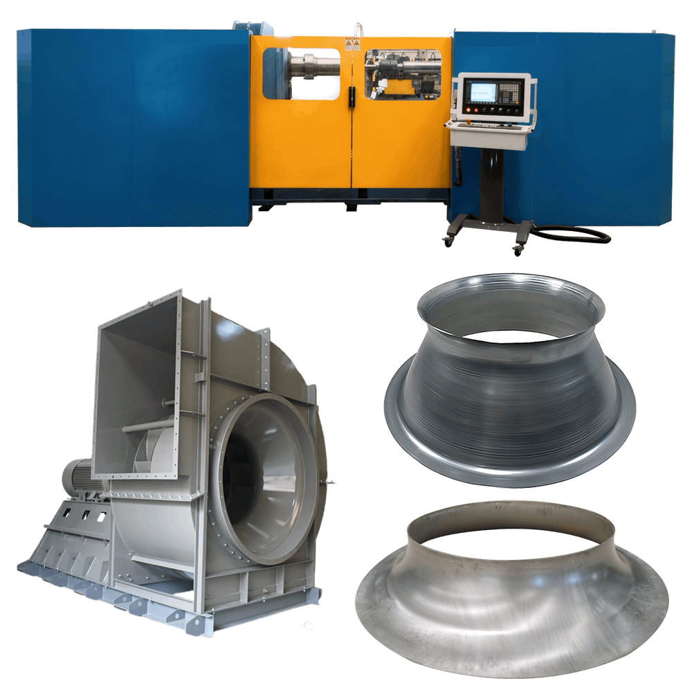
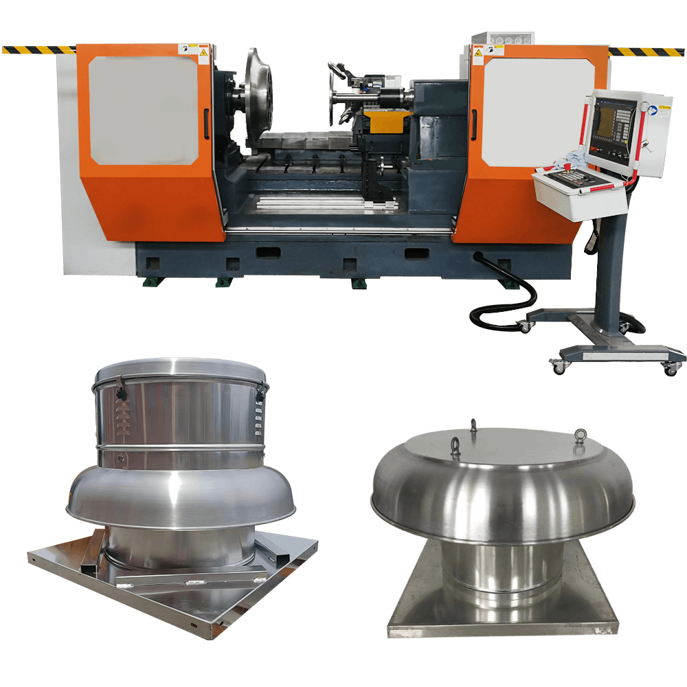
CNC Metal Spinning For Ventilations Industry Fans Impeller Shrouds
Altron tells you how to use CNC metal spinning for Ventilations past and industrial fan impeller shrouds!
From the design of spinning molds, mold installation, spinning machine debugging, spinning program writing, CNC spinning spinning machine operation to the detection and modification of the workpiece forming spinning program!
Industrial fan impeller shrouds can be spun materials: aluminum, carbon steel, galvanized sheet, stainless steel!
Imper Shrouds Metal Spinning Mold Design
According to the inner contour of the impeller shroud, the spinning mold and tooling should be designed. Different mold materials and processing processes should be selected according to the hardness of the processed material!
Common mold materials include CR12, 45#, etc.
- When spinning requires a higher inner contour accuracy, a solid mold full mold is used.
- Moldless metal spinning can be used for impeller shrous with small spinning batches and low requirements for inner contour accuracy.
Metal Spinning Mold and Mold Installation
- Clean the installation part of the mold, remove rust and impurities such as iron cuttings.
- For mold hoisting, cloth belt lifting and solid lifting rings are required. Remember not to use iron hooks and wire ropes.
- The mold and spindle connection need to use high-strength screws of grade 12.8 or above.
- After the mold is installed, check the runout accuracy of the mold, which cannot exceed 0.03mm. If there is a deviation, check the connection assembly size of the mold and whether the mold is installed correctly. Use the inspection and elimination method!

Mold Contour Measurement Points, Metal Spinning Program Preparation
- Straight line contour expresses one coordinate
- Oblique line contour calibrates two coordinate points
- Arc contour calibrates three points
Draw the coordinate points displayed on the spinning machine into the CAD software, and connect the point coordinates in series to generate the mold contour as a reference for the spinning trajectory.


Draw The Metal Spinning Trajectory

Input the mold data coordinates into the CAD software, and connect the mold contour in series to make a reference contour for the spinning path, so as to facilitate the drawing of the spinning trajectory!

Main Matters For Drawing Metal Spinning Trajectory
- Point-to-point line connection and arc link, points cannot intersect on lines and endpoints, otherwise the spinning code cannot be generated in the programming software.
- In addition to the spinning trajectory segments of four different layers in the DXF file of the spinning trajectory line.
- There should be no extra lines or points, which will affect the automatic generation of the program.

- The program code on the left can be transferred to the Siemens system of the CNC spinning machine through a USB flash drive or the Internet, and a dry run simulation can be performed.
- Observe the change in the gap between the spinning roller and the mold to see if it is consistent with the drawing! If there is a collision or deviation, the machine should be stopped in time, and the tooling and other related parts of the formed machine should be checked.
- Until the spinning process is running normally.
- Setting and coordinate determination of auxiliary tools on the CNC spinning machine, turning tools, cutting tools, rolling rollers, turning rollers, folding rollers, etc.

First Metal Spinning Test
- The worker places the metal disc material on the hanging structure of the machine.
- Start the automatic program switch and start running the program!
- After the spindle rotates, apply a small amount of stretching oil on the surface of the metal material to lubricate the spinning roller.
- Close the protective door of the CNC spinning machine to prevent iron chips and oil stains from splashing, and take protective measures! Complete the CNC spinning program to achieve automated production!

After The Metal Spinning Operation Is Completed

- Check whether the spinning parts fit the mold, which can be adjusted through CNC compensation of the program contour.
- Measure key dimensions and data.
- Observe the surface texture and details of the spinning. If the surface requirements are high, the running speed of the last section of the spinning path should be appropriately reduced.
- Adjust the size and diameter of the disc material, and optimize the size of the laser cutting blank according to the product data of the first spinning.
- Make a contour inspection gauge for laser cutting to check whether the hub curvature of the workpiece is correct.
 |
 |
 |
CNC Metal Spinning For Ventilations Impeller Shrouds Video
CNC Spun Metal Impeller Shrouds After Welding Preparation
- Make impeller blades according to the correct drawings.
- Spot welding assembly of impeller.
- Full welding using impeller welding robot
 |
 |
 |
Impeller Automatic Welding Robot Video
Altron’s Metal Forming and Welding Service Trends
Altron provides complete automated welding solutions and metal spinning for Ventilations & Industrial Fans manufacturers! Improve the quality and production efficiency of your industrial fans. Altron engineer Joby will always be with you in any case!
The spinning solution for industrial fan impellers hopes to help you solve practical problems!
The next issue will explain how the cone of the industrial fan inlet is made of moldless metal spinning forming and the operation process steps!
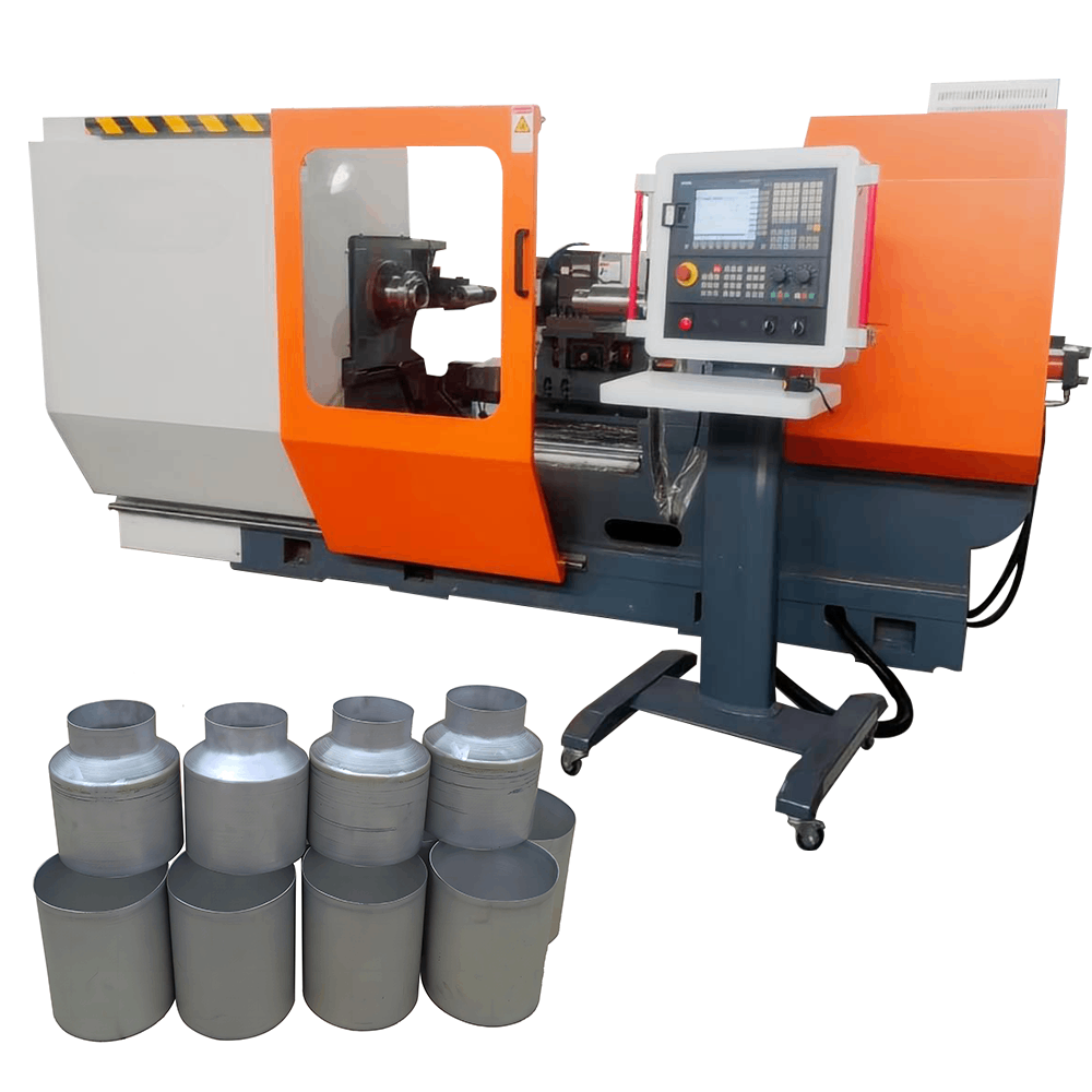
CNC Metal Spinning Machine -Single Roller AC1000
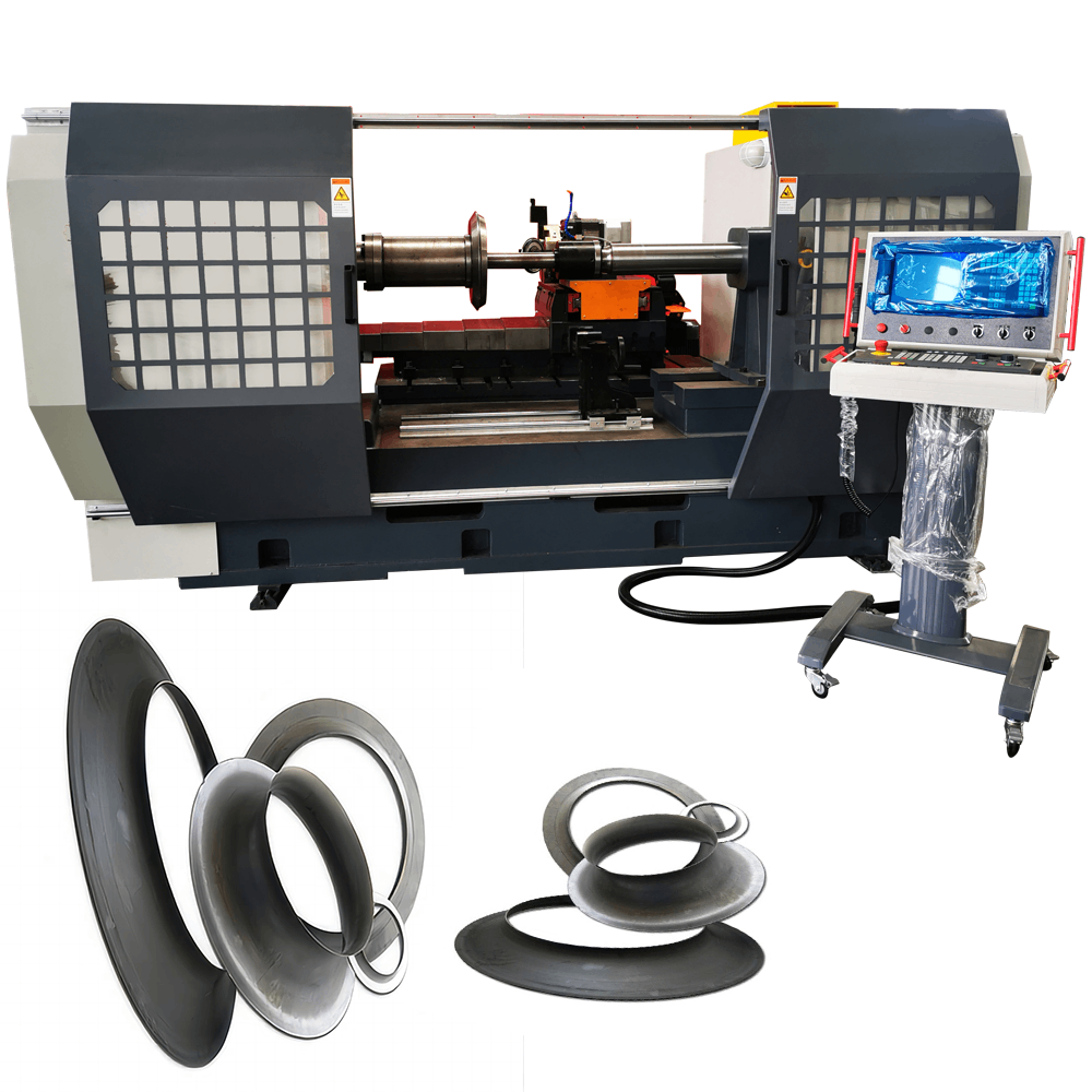
CNC Metal Spinning Machine -Single Roller AC1400
CNC Metal Spinning Machine -Single Roller AC1600